

A vertical conveyor carrier can support the required weight and still be the wrong design. The real question is where the product is supported and how the product enters and leaves the carrier. Product bottom shape, center of gravity, and transfer method therefore come before load rating alone.
Fork carriers work when the product has clear support points. Platforms or shelves provide broader bottom support. Powered roller or belt carriers can handle loads that need an active transfer surface.
Carrier geometry also sets the required carrier pitch. The largest approved product needs enough vertical and horizontal clearance to travel and transfer without contact, while excessive spacing reduces the number of carriers available per minute.
Good carrier design matches the product base, transfer interface, and required carrier frequency as one system—not as three separate choices.
Which Carrier Type Fits the Product?
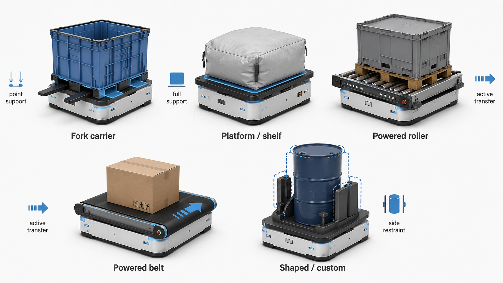
Carrier type starts with the product’s support surface. The key question is where the carrier can hold the load without interfering with infeed or discharge.
| Product / transfer condition | Carrier type to evaluate first | Critical design check |
|---|---|---|
| Rigid carton or tote with defined support areas | Fork carrier | Fork position, unsupported span, product bottom |
| Soft, flexible, or irregular package | Platform or shelf | Bottom support and deformation |
| Pallet with defined runners or openings | Fork or powered carrier | Runner spacing and transfer direction |
| Heavy tote or pallet requiring active transfer | Roller, belt, or chain carrier | Transfer surface and drive cycle |
| Round, tall, or unstable product | Shaped or custom carrier | Center of gravity and restraint |
| Large product-size range | Common-envelope or custom carrier | Min/max product compatibility |
Fork carriers support the load at selected points rather than across the full bottom. Fork position must match the carton base, pallet runners, or other structural support areas. The infeed and outfeed conveyor must also leave a clear path for the forks during transfer.
Platforms and shelves provide broader support when discrete forks would leave too much of the product unsupported. Soft packaging, irregular bases, and products with weak bottom panels are typical reasons to increase the support area.
Powered carriers add rollers, belts, or chains when gravity or passive transfer cannot move the load reliably. The carrier surface must match the load bottom and the adjoining conveyor so the product does not lose support at the interface.
For every carrier type, check the smallest and largest product, bottom contact area, center of gravity, transfer direction, and required clearances. Pallet runner spacing and carton bottom construction can matter more than the outside dimensions.
Carrier selection should also stay within the complete product and operating envelope defined in the vertical chain conveyor design and selection guide.
The right carrier is not the one that simply holds the load. The right carrier supports the correct parts of the load and still allows a clean transfer.
Match the Carrier to the Product Bottom and Center of Gravity
Carrier geometry should follow the product’s actual load-bearing surface, not the outside dimensions shown on a drawing.
A 600 mm-wide carton does not necessarily provide 600 mm of usable support. Recessed bottoms, ribs, feet, tape seams, damaged corners, pallet runners, or product overhang can reduce the area that can safely contact the carrier.
For fork or other discrete support, check:
- Effective support area: Locate the parts of the bottom that actually carry the load.
- Unsupported span: Confirm that the product bottom remains rigid between support points and while crossing the transfer gap.
- Pallet runners or stringers: Match carrier contact points to the structural parts of the pallet, not the pallet outline.
- Product orientation: A 90-degree rotation can move ribs, runners, openings, and weak areas away from the intended support points.
Center of gravity must be checked against the same support geometry. The projected center of gravity should remain inside the effective support polygon during pickup, vertical travel, and discharge. Tall, narrow, off-center, or unevenly loaded products need more attention because a small position error can move the center of gravity closer to a support edge.
For several products on one carrier, check the combined center of gravity as well as the position of each product. Guides can maintain orientation, but guides should not be used to correct a load that already sits outside the approved support envelope.
Design for the least favorable approved condition—not the best sample. Final carrier geometry should be verified from actual products or detailed bottom drawings showing support points, orientation, deformation, and the maximum permitted load offset.
Carrier Spacing and the Moving Envelope
Carrier spacing is a geometry decision before it becomes a capacity decision. First prove how much space the loaded carrier needs throughout the complete loop. Then determine how closely the next carrier can follow.
Do not check the product as a static length × width × height box. Check the moving envelope created by the product, carrier, guides, and any restraints. The complete envelope must clear:
- Adjacent loaded or empty carriers
- Conveyor frame and guarding
- The opposing carrier path
- Top and bottom return sections
- Infeed and outfeed openings
- Any guides, stops, or transfer mechanisms
Maximum product height usually has the strongest effect on carrier-to-carrier spacing, but width, carrier depth, product overhang, and transfer movement can also set the limit. The top and bottom return sections deserve separate verification because the carrier path changes direction there.
Only after the moving envelope is proven should the minimum usable carrier spacing be established. Do not confuse a manufacturer’s carrier mounting increment with the actual spacing available for loaded products.
Smaller spacing can bring carriers to the transfer point more frequently. Larger products, deeper carriers, or greater clearance requirements usually reduce that frequency. Published continuous-conveyor capacities therefore depend partly on product dimensions and machine configuration rather than carrier speed alone.
Adding carriers also stops helping once the infeed or outfeed cannot use every arrival. After the minimum feasible spacing is known, convert carrier spacing and travel speed into carrier arrival rate, then check transfer-cycle and sustained-capacity limits using the vertical conveyor capacity calculation.
Do not shrink the carrier pitch to chase capacity. Prove the moving envelope first, then calculate how much capacity the available spacing can actually support.
What Product Data Should Be Verified Before Finalizing the Carrier Design?
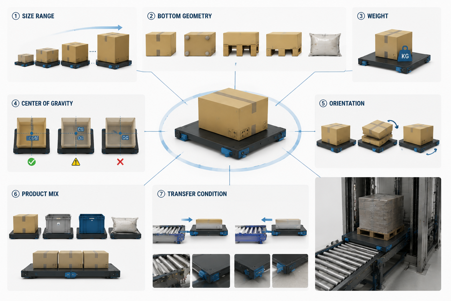
A carrier should not be finalized from one representative carton, tote, or pallet. The design must cover the worst approved combination of size, weight, bottom geometry, orientation, and load position.
| Product data | What to verify | Design impact |
|---|---|---|
| Size range | Minimum and maximum L × W × H | Carrier size and moving envelope |
| Bottom geometry | Contact areas, ribs, feet, runners, openings, flexible sections | Fork or platform support position |
| Weight | Minimum/maximum weight and load distribution | Carrier structure and support |
| Center of gravity | Normal and worst approved position | Stability and support margin |
| Orientation | Required infeed and discharge direction | Contact points and transfer geometry |
| Product mix | Approved SKUs and products per carrier | Common carrier envelope |
| Transfer condition | Conveyor type, direction, and handoff method | Carrier-to-conveyor compatibility |
Photos are useful, but detailed bottom drawings or actual samples are better when support geometry is not obvious. Pallet runners, tote feet, recessed carton bottoms, flexible packaging, and permitted product overhang can all change where the carrier can safely make contact.
Validation does not require testing every SKU when several products share the same handling characteristics. Instead, select the products that create the design limits: the smallest, largest, heaviest, tallest, least rigid, and least favorable bottom geometry, plus any permitted alternative orientation or multi-product loading condition.
Transfer conditions should then be verified with the loaded carrier using the same alignment and handoff criteria described in the vertical conveyor transfer design guide.
Do not approve the carrier because the average product fits. Approve the carrier only when the products that define the design limits fit and transfer correctly.
Practical Carrier Design Recommendation
A good carrier is designed around the product, not around a standard fork or platform size. The carrier must support the least favorable approved load, transfer cleanly at both ends, and leave enough moving clearance before carrier pitch is reduced for capacity.
Carrier spacing should be the result of proven product geometry—not the starting point for throughput.
Send CS Conveyor your product dimensions, weight, bottom photos or drawings, transfer direction, and target rate for a carrier design review and quotation.
Frequently Asked Questions
1. What is the difference between a fork carrier and a platform carrier?
A fork carrier supports the load at defined points, while a platform carrier supports a larger part of the product bottom. The better choice depends on bottom geometry, rigidity, center of gravity, and how the product transfers on and off the carrier.
2. How do I choose fork spacing for a vertical conveyor carrier?
There is no standard fork spacing for every product. Fork positions should match the actual load-bearing areas, pallet runners, ribs, openings, center of gravity, and the clearance required at the infeed and outfeed transfer points.
3. Can the same carrier handle different product sizes?
Yes, if every approved product fits the same support, guide, transfer, and moving-envelope limits. Large differences in bottom geometry or product size may require a custom or adjustable carrier.
4. How does product height affect carrier spacing?
Taller products usually require more clearance between loaded carriers. That can increase carrier pitch, reduce carrier arrival frequency, and lower theoretical capacity. Final spacing must also clear the top and bottom return paths.
5. Can one carrier hold more than one product?
Yes. Check product spacing, support, combined center of gravity, load distribution, and transfer time. More products per carrier can increase theoretical capacity, but longer loading or unloading cycles may limit the actual gain.
6. What information should I send for vertical conveyor carrier design?
Send the minimum and maximum product size and weight, bottom photos or drawings, support points, product orientation, center-of-gravity information where available, infeed and outfeed details, and required throughput. Product samples are useful when the bottom geometry or packaging behavior is difficult to judge from drawings alone.
Post time: Aug-14-2026


