

Vertical conveyor transfer design determines whether a unit load crosses the infeed or outfeed interface without losing support, position, or timing. A vertical conveyor transfer is the controlled handoff of a unit load between the lift carrier and an infeed or outfeed conveyor at a fixed transfer position.Correct lift height alone does not make a transfer reliable. The carrier, horizontal conveyor, sensors, and control sequence must reach the same transfer state at the same time. Every transfer point is a controlled handoff, not an open gap between two machines.
Product bottom condition, transfer gap, alignment, available support, and center of gravity determine whether the load crosses cleanly or tips, turns, stalls, or lands outside the carrier envelope. Infeed and outfeed transfers set part of the complete system cycle; vertical conveyor speed alone cannot define transfer capacity. A reliable design confirms support through the gap, carrier position, product arrival, downstream readiness, and fault recovery before transfer motion begins.
How Does a Vertical Conveyor Infeed and Outfeed Transfer Sequence Work?
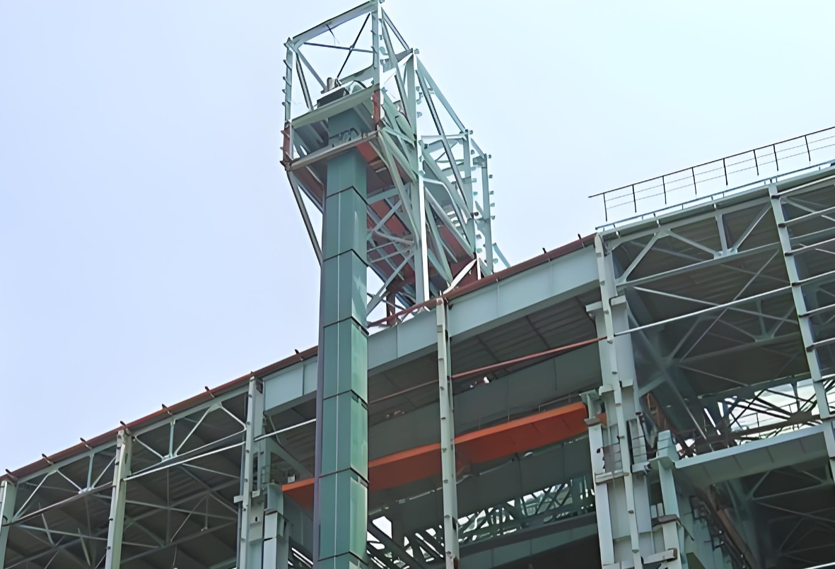
A reliable transfer is a confirmed sequence of conditions, not a single conveyor start command. The lift may be at the correct elevation, but transfer should not begin until the product is separated, the correct carrier is aligned, and the receiving path is available. Infeed and outfeed transfers are connected operating events: every product loaded must later be discharged without disrupting the carrier cycle or the surrounding line.The sequence must therefore match the carrier arrangement, product limits, and required flow described in this vertical chain conveyor design and selection guide.
| Sequence stage | Required condition | Control action |
|---|---|---|
| Product staged | One product is present, separated, and correctly oriented at the infeed stop | Hold the product until the carrier is ready |
| Carrier positioned | The carrier is aligned with the transfer conveyor at the correct level | Enable the transfer zone |
| Transfer path clear | No product or obstruction remains across the interface | Start the infeed conveyor or transfer mechanism |
| Loading confirmed | The complete product, including the trailing edge, has cleared the infeed interface | Stop the transfer mechanism and release vertical travel |
| Discharge confirmed | The downstream conveyor is ready, and the product has fully cleared the carrier | Stop outfeed motion and release the empty carrier |
Product arrival and carrier arrival should be confirmed by position signals rather than assumed from elapsed time. A product being detected inside the carrier is not sufficient if its rear edge remains across the interface. At discharge, downstream availability must be established before the product moves, and the carrier must be confirmed empty afterward.
Continuous systems must also verify that the expected carrier has arrived. Multi-level systems need destination confirmation before loading or discharge so that a valid product is not sent to the wrong level. When any required condition is not reached within the permitted sequence time, the system should stop the affected transfer, retain product position where practical, and issue a defined fault for controlled recovery.
How Should Carrier Alignment and the Conveyor Transfer Gap Be Designed?
The smallest conveyor transfer gap is not automatically the safest design. A reliable interface requires matched height, centerline, stopping position, and product support. Correct lift elevation alone cannot prevent a jam.
- Vertical alignment: The carrier surface and fixed conveyor must maintain the project-defined height relationship under design load. Installation error, loaded deflection, wear, and drive-system elongation can create a step at the interface. Alignment must be checked both empty and loaded.
- Lateral alignment: Conveyor centerlines, carrier centerlines, and guides must continue through the transfer point. A side offset reduces support on one edge and increases tipping risk for tall or narrow products.
- Carrier position: A stop command does not confirm transfer alignment. Position sensors, encoder feedback, or a mechanical locating device must confirm the usable carrier position before product movement begins.
- Transfer gap: Gap size depends on the smallest product base, bottom rigidity, required clearance, carrier movement, and transfer method. Too little clearance creates interference. Too much clearance allows the product to dip, rotate, or stall.
- Support continuity: The effective product base matters more than total product length. Damaged cartons, soft bags, open-bottom crates, and uneven pallets require separate checks. The projected center of gravity must remain inside the effective support area throughout the transfer.
- Guides and restraints: Guides must maintain product orientation without blocking carrier entry or discharge. Round, tall, or low-friction products require restraint when normal transfer forces can change product position.
Vertical Conveyor Transfer Gap and Alignment Example
Assume the carrier is installed 2 mm below the fixed conveyor. An illustrative 4 mm loaded deflection increases the operating height difference to 6 mm.
A rigid carton with a 400 mm base length crossing a 35 mm transfer gap has an unsupported interface equal to:
The calculation does not prove that the transfer is safe. The calculation shows why installation tolerance, loaded deflection, gap size, and product-base rigidity must be reviewed together. A soft carton or uneven base can fail at the same interface even when a rigid carton crosses successfully.
Transfer plates, nose rollers, powered belts, or powered roller sections can improve support continuity. Every interface must still be tested with the smallest, largest, and least stable approved product.
Which Sensors and Timing Signals Control a Vertical Conveyor Transfer?
Transfer control needs proof, not prediction. A timer shows how long a command has been active; a sensor confirms what physically happened. Product position, carrier alignment, path clearance, and downstream availability must all be confirmed before transfer motion begins.
| Signal | What the signal must confirm | Fault response |
|---|---|---|
| Product ready | One product is staged, separated, and correctly oriented | Hold the infeed sequence |
| Carrier aligned | The carrier is inside the approved transfer position | Block product movement |
| Transfer zone clear | No product or obstruction remains across the interface | Stop the transfer |
| Loading complete | The full product, including the trailing edge, has entered the carrier | Hold vertical travel |
| Downstream ready | The receiving zone is clear and able to run | Hold the carrier |
| Discharge complete | The product has fully cleared the carrier and outfeed zone | Block carrier release |
| Drive feedback | The commanded conveyor or transfer device is moving correctly | Stop and issue a fault |
A product-present sensor cannot confirm carrier position. A carrier-position signal cannot prove that the product has cleared the interface. Each signal must confirm one physical condition.
Carrier alignment can use position sensors, encoder feedback, absolute position data, or mechanical locating. Continuous carrier systems require position tracking for the correct circulating carrier. Multi-level systems also require destination confirmation before discharge.
Vertical Conveyor Transfer Sensor Position Example
Assume a product moves at 0.6 m/s and the combined sensor, PLC, output, and drive response takes 100 ms.
The product moves another 60 mm after detection. A sensor installed only 20 mm before the required stopping point cannot produce accurate staging under those conditions.
The final sensor position must account for:
- Conveyor speed
- Total control and drive delay
- Product-length variation
- Belt or roller slip
- Required stopping tolerance
The 100 ms value is an illustrative project assumption, not a standard sensor response time. Actual delay must be measured or confirmed from the selected controls and drive system.
Sensor technology must also match the product. Dark, clear, reflective, perforated, flexible, or irregular packages can produce unreliable switching with a basic single-point photoelectric sensor. Opposed-mode sensors, retroreflective sensors, clear-object sensors, light arrays, or vision systems should be selected from the actual product surface, shape, speed, and position range.
Timers remain useful for fault limits. A timeout can detect a missing product, incomplete loading, blocked discharge, or carrier-position failure. A timer cannot replace confirmed product, position, clearance, or drive feedback.
How Should Vertical Conveyor Transfer Design Be Verified Before Commissioning?
An empty-cycle test proves that the equipment can move. An empty-cycle test does not prove that products can transfer at the required rate. Final verification must use loaded carriers, approved products, normal production timing, and expected fault conditions.
Testing should cover the following conditions:
- Loaded alignment: Check carrier height, centerline, and stopping position at every transfer level with an empty carrier and the maximum design load.
- Product range: Test the smallest, largest, heaviest, least rigid, and least stable approved products. Each load must cross the interface without tipping, stalling, impact, product damage, or false sensor confirmation.
- Arrival timing: Test early, late, and uneven product arrival. Metering and carrier controls must prevent doubled loads, missed carriers, and partial loading.
- Blocked discharge: Stop the receiving conveyor or occupy the discharge zone. The vertical conveyor must hold the load instead of releasing the product into a blocked interface.
- Interrupted transfer: Test incomplete loading, blocked sensors, timeouts, and emergency stops. Restart must begin only after product position, carrier position, and transfer-zone status are confirmed.
- Sustained operation: Run consecutive cycles at the required production rate. Record missed transfers, product damage, timeouts, jams, and unplanned stops.
- Safety and access: Verify guards, doors, interlocks, inspection access, cleaning access, and jam-recovery points under safe isolation conditions.
Testing only the easiest carton can hide transfer-gap, alignment, support, and sensor problems. The test range must represent the full approved product range, including the worst base condition, highest center of gravity, and most difficult surface to detect.
Before testing begins, define the required rate, test duration, permitted stoppages, product-damage limits, fault response, restart method, and acceptance criteria.
A vertical conveyor transfer is ready for commissioning only when every approved product transfers at the required sustained rate and expected faults produce a safe, controlled response.
A reliable vertical conveyor transfer is designed from the product outward, not from the sensor list inward. Product base, center of gravity, size range, carrier support, and transfer gap determine whether the load can cross the interface; sensors only confirm that the required conditions exist. Final approval requires loaded alignment, sustained cycles, blocked discharge, missed detection, interrupted transfer, and controlled restart with the least stable approved product. Send CS Conveyor your product data, target rate, lift height, and layout for transfer design review and quotation.
Frequently Asked Questions
1. How large can a vertical conveyor transfer gap be?
No universal maximum conveyor transfer gap applies to every product. The acceptabgap depends on the smallest product base, bottom rigidity, center of gravity, carrier movement, required clearance, and transfer method. Final gap approval requires loaded testing with the smallest and least stable approved products.
2. Do the infeed and carrier conveyors need to run at the same speed?
Identical speeds are not always required, but the speed relationship must remain controlled. Product friction, transfer distance, required spacing, and stopping position determine the correct speed relationship. An unverified speed difference can cause sliding, rotation, impact, or incorrect placement inside the carrier.
3. How many sensors does a vertical conveyor transfer need?
Sensor count follows the required physical confirmations, not a standard number. The control sequence normally needs separate proof of product readiness, carrier alignment, transfer-zone clearance, downstream availability, and completed transfer. One product sensor cannot reliably confirm every condition or replace carrier-position feedback.
4. Why does a product jam when the carrier is at the correct level?
Correct elevation does not prove complete transfer alignment. Vertical offset, lateral offset, excessive gap, weak product support, loaded carrier deflection, guide interference, speed mismatch, or incorrect timing can still cause a jam. Troubleshooting must inspect the complete mechanical interface and control sequence, not only the lift position or sensors.
5. What should happen when the downstream conveyor is blocked?
Outfeed motion must remain disabled while the receiving zone is occupied. The carrier must hold the product, while the control system stops, meters, accumulates, or diverts upstream flow according to the approved sequence. Restart requires fresh confirmation of carrier position, product status, and downstream clearance.
6. Should transfer testing use actual products?
Transfer testing should use actual products whenever available. Representative samples are acceptable only when dimensions, weight, bottom condition, rigidity, center of gravity, and surface properties match the approved loads. Testing must include the smallest, largest, least stable, and hardest-to-detect product—not only the easiest carton.
Post time: Jul-31-2026


