

A vertical reciprocating conveyor moves a load between fixed elevations on a carriage or platform that travels up and down along guide columns. Unlike a continuous vertical conveyor, the carriage does not circulate through a closed loop; it completes one loading, vertical travel, unloading, and repositioning sequence before the next transport cycle is completed.
The working principle therefore depends on the complete carriage cycle, not vertical travel speed alone. Drive system, carriage guidance, level positioning, infeed and outfeed transfers, sensors, controls, and safety interlocks must operate as one coordinated sequence.
What Is a Vertical Reciprocating Conveyor and How Does It Work?
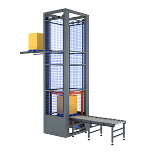
A vertical reciprocating conveyor uses a guided carriage or platform to support cartons, totes, pallets, fixtures, or other unit loads during vertical movement. The carriage travels along one or more guide columns so that it remains aligned with the loading and discharge levels.
Lifting force may be provided by a chain-driven mechanical system, cable mechanism, screw drive, or hydraulic system depending on the conveyor design. The drive raises and lowers the carriage; it does not continuously circulate the product around a vertical loop.
The carriage may use a plain platform for manual loading or include powered rollers, chains, or other transfer equipment for automatic infeed and outfeed. A complete reciprocating lift conveyor therefore combines the lifting mechanism with carriage guidance, level positioning, transfers, controls, and safety devices.
What Happens During a Complete Reciprocating Conveyor Cycle?
A complete operating cycle normally follows this sequence:
Load ready → carriage positioned → load enters → transfer confirmed → vertical travel → destination positioning → load exits → carriage repositions
1. Load ready
The product reaches the infeed position and waits until the lift is available.
2. Carriage positioned
The carriage reaches the loading level and stops at the required transfer position.
3. Load transfer
The product moves from the infeed conveyor onto the carriage.
4. Transfer confirmed
Sensors or control signals confirm that the load is completely inside the carriage and the transfer path is clear.
5. Vertical travel
The drive moves the loaded carriage along the guide columns to the required elevation.
6. Destination positioning
The carriage stops and aligns with the destination conveyor or unloading level.
7. Discharge
When the downstream position is ready, the product transfers out of the carriage.
8. Repositioning
The carriage returns to the loading level or moves to another requested level for the next cycle.
This complete sequence determines usable throughput. For example, if vertical travel requires 8 seconds but loading, positioning, unloading, and repositioning require another 12 seconds, the operating cycle is 20 seconds, not 8 seconds. This is why a vertical conveyor capacity calculation must use the complete carriage cycle rather than lift speed alone.
What Controls Reciprocating Conveyor Performance and Reliability?
Four areas have the greatest influence on reliable operation.
Drive and carriage guidance: The drive must support the required load, travel, acceleration, and duty cycle, while the guide system keeps the carriage stable throughout the stroke. Mechanical and hydraulic designs use different drive arrangements, but both must control the carriage through the complete movement.
Level positioning: Reaching approximately the correct height is not enough for an automatic transfer. The carriage must stop at a repeatable position that keeps the carriage surface aligned with the fixed infeed or outfeed conveyor.
Transfer and control sequence: Product presence, carriage position, transfer-zone clearance, loading completion, destination availability, and discharge completion must be confirmed in the correct order. Poor alignment or incorrect timing can stop the conveyor even when the lifting mechanism itself is operating normally. These interface conditions should be checked as part of the vertical conveyor transfer design.
Complete cycle time: Throughput is controlled by how many loads can complete the entire carriage cycle, not by maximum lifting speed. Longer travel, additional levels, slow transfers, waiting for downstream equipment, or repeated repositioning all increase cycle time.
A vertical reciprocating conveyor should also not be confused with a continuous vertical conveyor. A reciprocating system moves one carriage back and forth between levels, while a continuous system circulates multiple carriers through a closed path. Their motion, loading opportunities, and capacity calculations are therefore different.
A vertical reciprocating conveyor works reliably only when the carriage, drive, guides, transfers, controls, and safety sequence operate as one system. Define the load, carriage size, vertical travel, required levels, transfer arrangement, and target cycle time before finalizing the conveyor configuration.
Post time: Apr-11-2024


